显示标签为“Kess V2 Master”的博文。显示所有博文

2018年3月4日星期日

How to update Ktag firmware to version 7.020

Updating KTAG firmware to 7.020 version doesn’t block processor.
For correct operation device it is necessary to change CID SDcard on 035344535330344780399b1368010300
This procedure is supported by not each SDcard.
Programs for change of CID and the description of process easy to find in the Internet.
I used mmc32 and evoplus_cid from github. This programs for linux. I haven’t found soft working in Windows
It is difficult to find SDcard which supports change CID.
SDcards with built-in chipset of production Samsung meet such requirements.
22-1
CID SDcard: 035344535330344780399b1368010300
Firmware_7.020: https://mega.nz/#!rUdDnYDA!RrHb5a8CcksLq22Yl9r-sjwZ-FUfAZV44odW-1N62xQ Ksuite_2.23: https://mega.nz/#!OZVWVKaB!69SeNOiikVGqZLx2Fxy7-KMZ4s7-0Zi9WjzDCFQSL1s
mmc32: https://mega.nz/#!DFN2DLBb!-xLw3pgRAULLx3ggvo7WKAbwCHSjypwZyaLoD9-XuKE
Ktag fw 7.020 update FAQs:
Q: for upgrade KTAG ECU Programmer with 6.070 required change nxp whit crp3 status?:
A: if you use Jlink to you necessary level not above CRP1
if you use usb-com to you necessary level not above CRP2
Q: tool trick is test unlock whit airflow?
A: Yes, but sometimes it’s easier to replace LPC with new device.
Q: trick airflow whit my kess not work…send me instruction for test on ktag and i’m test trick on ktag…thanks. And i have a question…problem is my ftdi interface?
A: I think most simply to change NXP processor.
…temperature destroys the processor
It is very doubtful method
Q: After you change cid copy image with sd
A: cloning of SDcard is a big problem now
I will do SDcard for CID
Q: what linux system did you use?
A: linux version will not matter
Q: what program do the card image sd ??
A: I used mmc32 and evoplus_cid from github. This programs for linux.
Q: i have samsung 64gb change the cid an uplad the bin but all i have is this on the picture. any ideas?
A: use up to 8gB card. And check all Made in Korea for rewritable CID
Q: what was the hardware problem ???
A: not all china clones are the same, mine is missing a few components
with ktag 6.070 from CnAutotool not have problems
there is free rework guide on the net
so i add them and all ok
Q: Can you share usb-com connections?
A: Here you go
22-5
NOTE: Good experienced technique is required. YOU ARE TRYING ALL ON YOUR OWN RISK. If you want a Ktag firmware 7.020 with relief and use it with security, go for a tested and working one – RED Auto ECU Programmer Ktag 7.020 is cost-effective. Look here: http://www.cnautotool.com/category-198-b0-KTAG.html
Confirmed! Working no issues!
22-2
22-3
22-4

Ktag 7.020 review deleted DPF, EGR, DTC successfully

Finally received my Ktag package. It’s firmware 7.020 master version. and tested on three cars today today.
See my Ktag fw 7.020: looks good
29-1 29-2
Now, i’ll chip in some words of my experience.
Three ECUs i’ve tested:
ISUZU ECU Transtron 4JJ1
Mazda Denso ECU RF8P
Hino 700 Denso Diesel ECU
Attached pictures here. Here you go…
Transtron 4JJ1 SH7058 ISUZU (P430):
without sensors
29-4
29-5
29-6
Ktag deleted DPF&EGR: success!
Mazda Denso RF8P (P277):
29-8
29-9
29-9
k-tag Fw 7.020 deleted DPF & Lambda: success
Hino 700 Denso Diesel ECU (P347):
29-10
29-11
Ktag v7.020 DPF & EGR and DTC deleted: success
In summary, i’m satisfied! This ktag works good for me, without issues.
Later, i’ll test on more (Mercedes S Class W221 ME9.7 ECU, Vw passage 1.6 TDI pcr2.1, etc.)

http://obdscanner.info/2018/02/25/ktag-7-020-review-deleted-dpf-egr-dtc-successfully/

KtagKess unlock CRP3 LPC2478 via J-link (Pinouts attached)

As you know, for crp3 we can do the trick for unlock crp3 heating on KTAG or KESS V2 programmer or buy a new NXP and write it (only one time)
Here are some questions & answers on Google form, questions about “how will you use J-ink if its crp3 ?”…
Q: Can I update NXP directly if at this moment I have Ktag 6.070? Or I will need to replace it with new one and then to update to 7.030 ?
A: if your actual fw is crp3 you will have to do “heating trick ” or change nxp, you will know if jlink doesn’t recognise firmware ( i think message about cannot find cpu chain or something like that) , simple
Q: More information this real version or china version? and whats this you can update or or only talk?? thanks
A: this is fw 7.030 we are talking about REAL firmware, not modding number in sw or similar, about second question i don’t understand what you ask.
Q: Need connect 12v ? my led red always off if not connect 12v
A: LED needs to monitor the state of the processor and it must be switched by the controller. If you do not have the power on the controller when connected by USB, then connect the other power source.
Q: How work on ktag ECU Chip Tuning, i tried but led already on
A: LED need to monitor the state of the processor and it must be switched by the controller. If you do not have the power on the controller when connected by USB, then connect the other power source.
To flash the LPC2478 via J-link, the level of protection should be CRP0, ie protection should be disabled. If security levels CRP1 and CRP2 have the ability to erase and reflash LPC2478 via UART, eg via USB to UART TTL adapter ftdi232 or cp2102 and Flashmagic program.
Q: LPC2478 connect Flash Magic, KESS or KTAG?
A: …KESS V2 & KTAG…both ok
Note: not all ktag 5.001 can be read with j-link
some are crp3 protected
some are not
Attachment 2: Here are all pinouts
A method of disabling the protection CRP3 microcontroller LPC2478…. make a photo high resolution of connection on pcb of that wire…and also,what pin you must to touch on nxp
28-1
28-2
K-Tag pins.
28-3
Attachment 3: Photos ofLPC2478 connect Flash Magic
It allows you to erase the NXP MCUs on both Kess & KTag via UART0. This will work for firmwares up to CRP2. CRP0, best off using J-Link as it only takes 30s as opposed to 30 minutes. If you’ve blocked your KTag properly (CRP3), it won’t help you. You will need to swap the processor.
Kess V2 connection method 1:
28-4
Kess V2 www.cnautotool.com connection method 2:
28-5
KTag connection:
28-6
Disclaimer: Photography of Pinouts is not mine. I am not responsible for a bad use.
http://obd2scantool.info/2018/02/25/ktagkess-unlock-crp3-lpc2478-via-j-link-pinouts-attached/

How to use BDM adapters with Ktag Kess KTM100 Dimsport

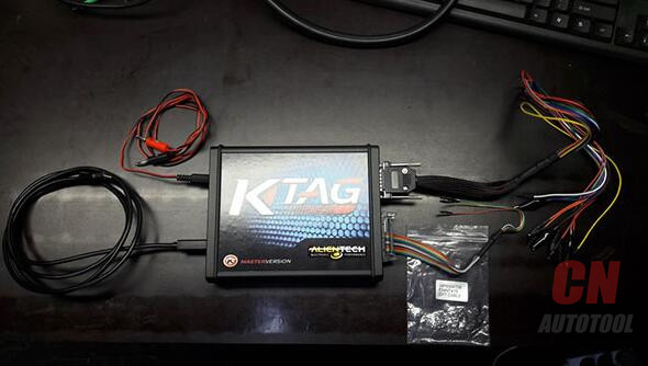
Here is a BDM adapter user manual for Denso, Marelli, Bosch, Siemens.
BDM probe adapters full set for sale:
http://www.cnautotool.com/
contact via Email: Sale@cnautotool.com
What is BDM?
BDM is an acronym for Background Debug Mode, an interface designed by the Motorola company, widely
used in automotive industry, present on modern ECUs. Not all ECUs are capable of interfacing
through the BDM – see Appendix for the list of ECUs that support the BDM interface.
What is Adapter?
ADAPTER is an electronic circuit board designed for a certain ECU (manufacturer), with pogo pins and a 10-pin IDC connector for interfacing the multiplexer board.
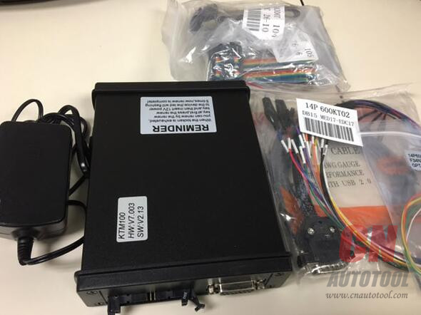
What is a BDM Adapter?
BDM adapter is an electronic circuit intended for BDM operation on supported ECU. The adapter provides pogo pin based connectors for interfacing the ECU BDM connector. Interfacing the supported tool is made by the use of intermediate circuit board (multiplexer) that connects to the adapter over the MUX connector and to the tool over the desired tool connector (FGTECH, 
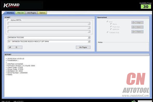
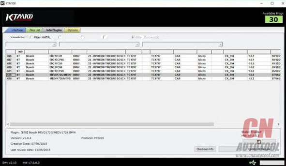
XPROG, BDM100,Dimsport, KTM100, KESS V2 & K TAG, etc.)
26-1
26-2
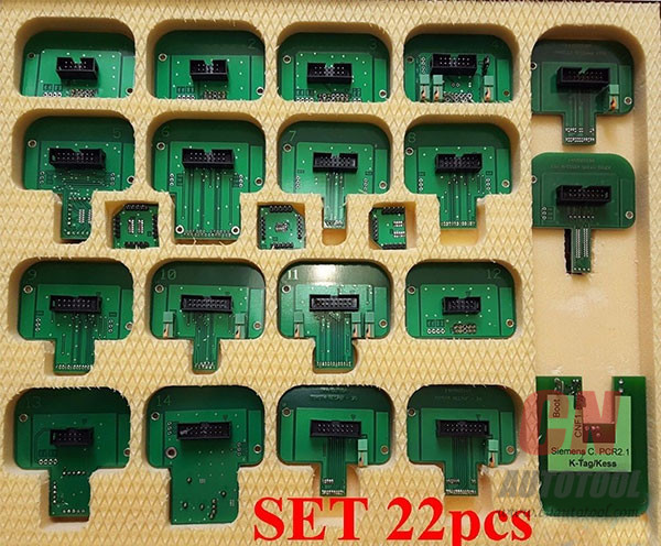
What is a BDM Adapter Full Set?
Here is a list of BDM adapter full set: (support Denso, Marelli, Bosch, Siemens)
A full set includes 22pcs.
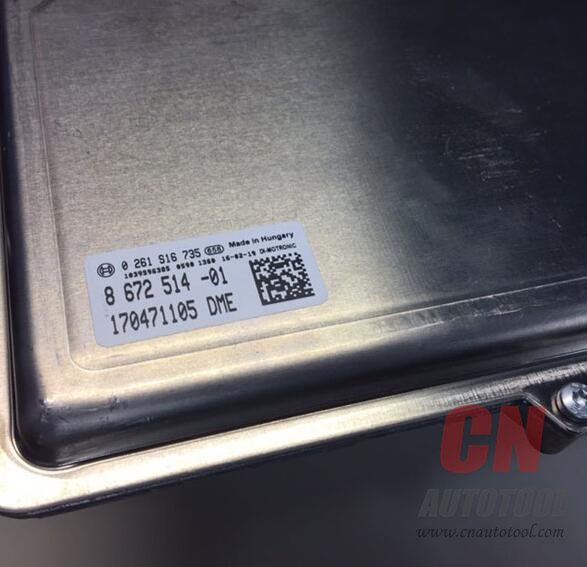
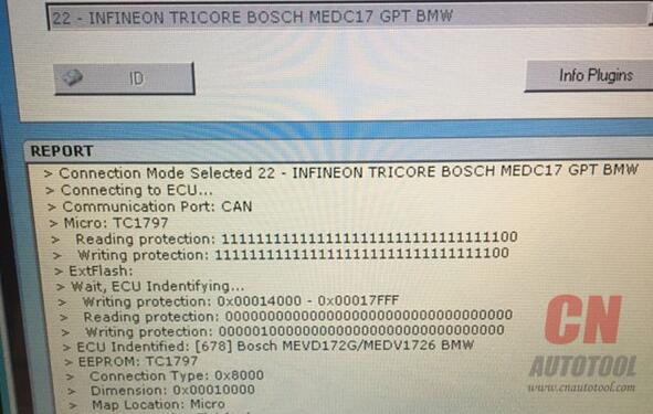
26-3
1 14AM00T01M Bosch
2 14AM00T02M Delphi DCM
3 14AM00T03M Bootloader ST10xx
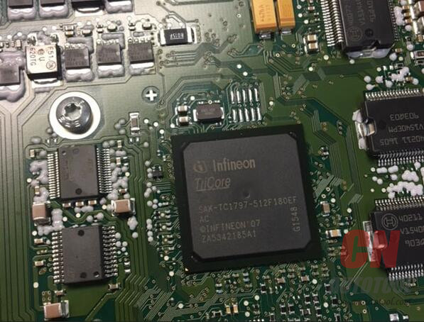
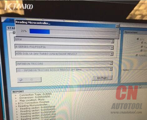
4 14P600KT04 Infineon Tricore EDC/MED17
5 14AM00T05M Marelli MPC55xx JTAG
6 14AM00T06M Delphi MPC55xx JTAG
7 14AM00T07M Denso CN1 Boot
8 14AM00T08M Denso CN2 Boot
9 14AM00T09M Denso CN3 Boot
10 14AM00T10M Denso CN1 AUD
11 14AM00T11M Denso CN2 AUD
12 14AM00T00M Delphi DCI
13 14AM00TBAS Base Adapter 1.27
14 14AM00T14M NexusEFI T6 Lotus
15 14AM00TB02 Magneti Marelli BDM insert
16 14AM00TB01 Siemens BDM insert
17 14AM00TB03 EDC7 BDM insert
18 14AM00T18M Magneti Marelli MPC/SPC56xx
19 14AM00T13M Nexus MPC5xx TRW ECU
20 VAG 1.6tdi – Siemens-Continental PCR2.1
21 14AM00T15M Toyota NEC76F-20
22 14AM00T16M Toyota NEC76F-26
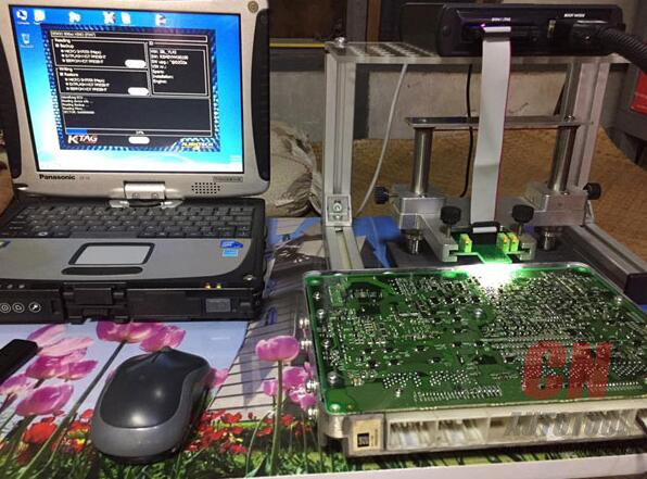
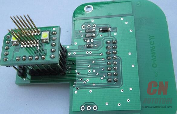
How to use a BDM probe adapter with KTAG/KESS/KTM100/Dimsport?
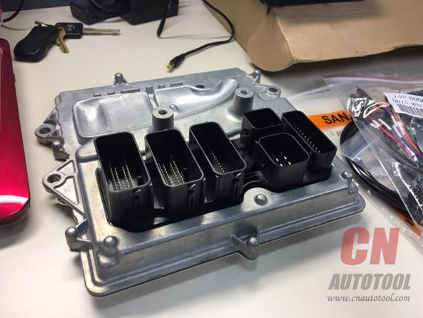
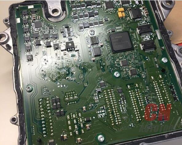
1.Open the ECU
○ at least one part of the casing (top or bottom) needs to be removed
○ refer to other sources (Internet) to get information on which part needs removing on your ECU
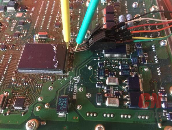
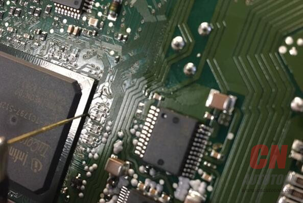
2.Locate the ECU BDM connector
○ usually a set of 10 – 12 pads in two rows (depending on the ECU)
○ pads may be 2.54 mm or 1.27 mm apart (depending on the ECU)
○ rows may be 2.54 mm or 5.08 mm apart (depending on the ECU)
○ if the ECU BDM connector can not be located, chances are that the BDM pads are scattered all over the ECU PCB in which case you can not use the adapter directly – nevertheless it is possible to manually route the adapter BDM signals to the ECU BDM pads (only for advanced users)
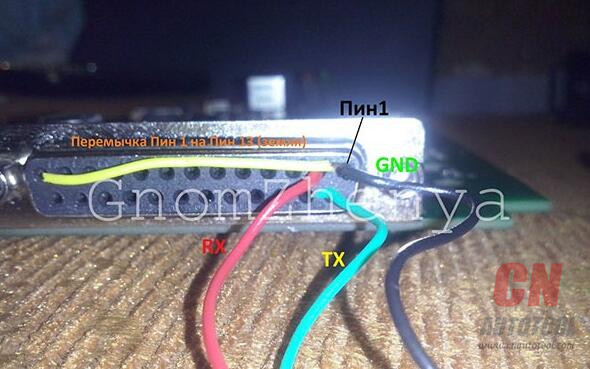
3.Locate the ECU BDM pin 1 position
○ pin 1 is usually not clearly marked on the ECU BDM pin out
○ on an ECU with the standard Motorola BDM pin out pins 3 and 5 are connected to ground – this can be checked either visually or using a multimeter tool
○ refer to other sources (Internet) to get more information on the pin 1 position for your ECU from CnAutotool.com
4.Place the desired adapter in the frame saddle
○ make sure the pogo pins are facing out
○ lift the saddle so that the ECU can be slided under the frame adapter saddle
5.Place the ECU on the frame
○ inspect the adapter for pogo pin 1 location which is clearly marked ○ rotate the ECU on the frame so that the adapter pogo pin 1 and ECU BDM pin 1 match
○ make sure ECU is firmly sitting on the frame
○ double check the ECU position
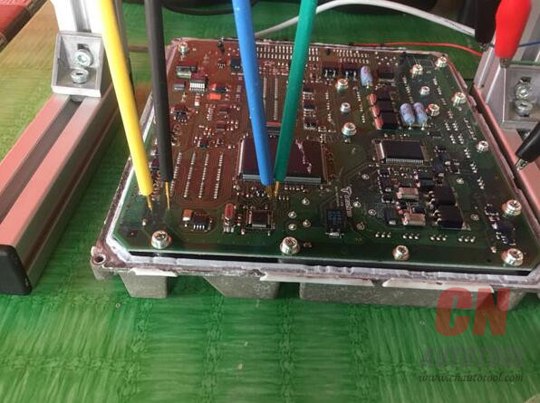
6.Connect the multiplexer board and adapter
○ at this point multiplexer board should be connected to the adapter via MUX connector
○ this will allow LEDs on the adapter to illuminate the area of interest (where the pogo pins need to touch the ECU BDM pads)
○ do not connect the tool yet
7.Connect the external power (+12 V) to the multiplexer
○ multiplexer external power is used to power the LEDs on the adapter allowing easier positioning of the adapter pogo pins on the ECU BDM pads
○ red LED on multiplexer board will light up when external power (+12 V) is present
○ at this point the white LEDs on the adapter should also light up
○ do not connect the tool yet
8.Fine tune the ECU position
○ lower the frame adapter saddle to almost touch the ECU BDM pads
○ each adapter pogo pin needs to sit on a separate ECU BDM pad
○ if pogo pins do not sit on the pads you may be using the wrong adapter – do not use the adapter in this case!
9.Lower the frame adapter saddle
○ each adapter pogo pin should sit on one ECU BDM pad
○ minimum down force should be applied when making the interconnection between the adapter and ECU
10.Double check the adapter pogo pin and ECU BDM pad interconnection
○ in order not to damage the ECU and/or tool make sure that the steps above have been performed correctly
11.Connect the tool to the multiplexer board
○ only connect one tool at any given moment to the multiplexer
○ make sure to use the correct 10-pin IDC connector (FGTECH, XPROG, BDM100&KTAG)for interfacing the tool used:
1 use provided 10-pin to 10-pin cable with FGTECH or BDM100 tools
2 use provided 10-pin to 16-pin cable with XPROG tool
3 use manufacturer 10-pin to 25-pin cable with KTAG tool
○ do not connect the tool to the 10-pin IDC connector labeled MUX
○ do not power up the tool yet
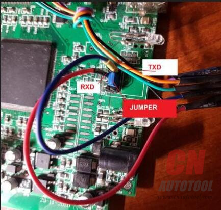
12.For Bosch adapter only
○ Bosch ECUs need to have ECU power supplied on the pogo pins (2 and 9)
○ some tools provide dedicated ECU power (BDM100, KTAG) while others do not (XPROG, FGTECH)
○ Bosch adapter can be used in both cases, providing that the jumper is properly placed on the 3-pin header (found on the adapter)
○ place the jumper on the adapter on the 3-pin header to the correct position:
○ place jumper over left and central pins when using XPROG and FGTECH tools – this will use +12 V power delivered from the multiplexer board (external power) for powering the ECU
○ place jumper over right and central pins when using BDM100 or KTAG tools – this will use +12 V power delivered by the tool for powering the ECU
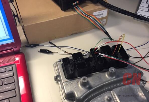
13.For Siemens, Delphi and Marelli adapters only
○ Siemens, Delphi and Marelli do not provide ECU power on the pogo pins
○ in order to power the ECU +12 V and ground signals needs to be connected to the ECU separately(usually over the ECU interfacing connector)
○ in this case ECU power can be taken from multiplexer board connectors J2 (+12 V) and J3 (ground), otherwise provide the +12 V ECU power from additional source
○ refer to other sources (Internet) to get more information on the location of the +12 V and ground pin location for your ECU
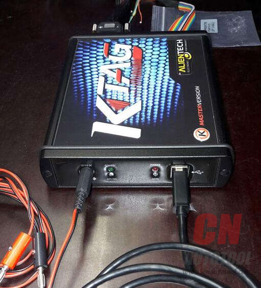
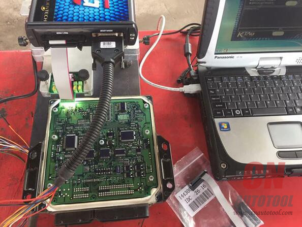
14.Connect the tool to the PC (or power up the tool)
○ perform software installation as described by the tool manufacturer if not done already
○ at this point the multiplexer, adapter and the ECU should be properly interconnected with BDM signals and power lines
1 multiplexer red LED should be lit up
2 adapter white LEDs should be lit up
3 ECU power (+12 V) should be present
○ connect the tool to the PC (usually done over USB or serial connection)
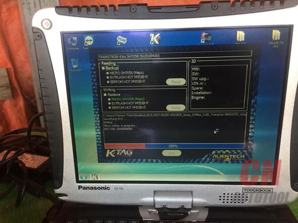
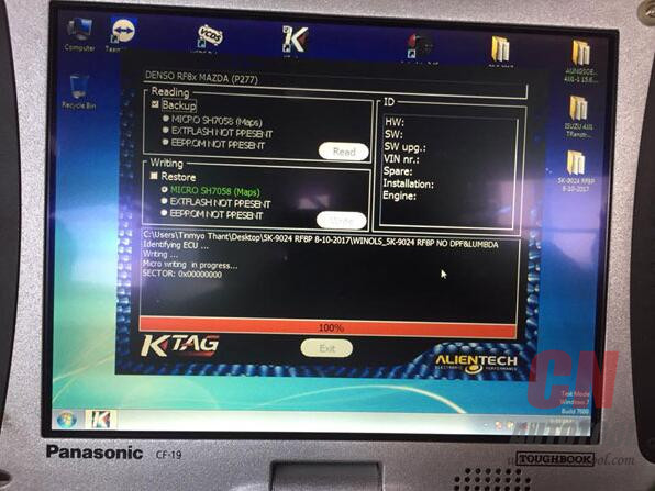
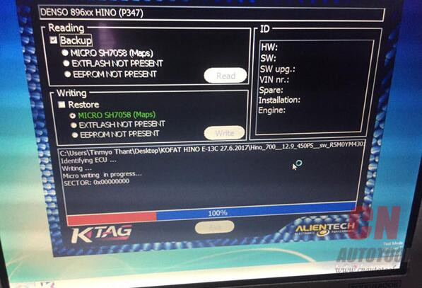
15.Perform BDM operation(s)
○ start up the software package to operate the ECU Programmer
○ perform desired BDM operation(s)Note: The user manual is used for reference; in fact, it depends. Try on your own risk.

http://autotool.biz/2018/02/25/how-to-use-bdm-adapters-with-ktag-kess-ktm100-dimsport/

Read and Write BMW Bosch DME MEVD172G with KTAG KTM100

Purpose:
DIY – DME/ECU Read Write and Tuning  2016MY F82 M using KTAG KTM100 master clone ecu tuning tool.
Disclaimer: Credit to su_root on bimmer forum provided the document for educational purposes. We are not responsible for any direct or indirect damage that may occur to your property as a result of the information provided here.
Parts arrived this morning. Below are pictures of what was included in the box.
–KTAG KTM100 Clone (US$349)
-12v/1A AC Adapter
-USB2.0 A-to-B Cable
-Cables to wire up to the DME
27-1 27-2
Software setup:
The instructions provided recommend the use of WinXP/Win7, disabling all network connections and malware detection programs. I was in a rush to stage the software and connect the flashing tool to ensure all was OK so I tested the following setup on a Win10Pro x64 machine. I also made the changes below before starting:
-Disable Driver Signature Enforcement – REQUIRED or Dimsport driver will not install and device will show as ‘Unknown’ under Device Manager
-Disable AV/Malware Software – I use Webroot/Defender and shut them off
-Disable LAN/WLAN adapters
After making the changes above to my PC I powered up the adapter and plugged in the USB cable. Windows warned me of the unsigned driver and continued the install.
Bringing up Car Diagnostic Tool KTM100 I see all is recognized correctly. You can also see below that the DME is supported and a plugin is available to communicate with that DME and calculate the correct checksum. Ready to start!
27-3
27-4
On Sunday I was able to get the car on the dyno and grab some factory numbers.
Phase 1 – Reading the DME:
Here she is. Bosch MEVD172G DME.
Below are a few pictures of the outside of the unit. I cleaned up a bit of sand around the unit to make sure nothing gets in while I attempt to open it up.
27-3 27-527-6
After about 30 minutes with a small blade going around the edges of the unit I was able to open the casing up. Luckily the components are not close to the edge of the case so as you’re going around it with a blade you don’t have to worry too much. But as always be careful not to jam the blade too deep; you may accidentally damage some of the surface mounted components.
27-7 27-8
Wired up the unit to the ECU Programming Tool KTM100 clone using the PDF attachment I posted earlier. Reading procedure is as follows:
1. Connect wires from the provided harnesses to the DME pins as shown in the Bosch PDF including BOOT pin.
2. Power ON KTM100 and connect to USB on PC
3. Launch KTM100 Application
4. Connect the harness side of the cables to the KTM100
5. Click ‘ID’ in KTM100 Application to verify DME communication.
6. Done. Now you can carry out the function you need (read/write/etc)
27-9 27-10
27-11
27-12
Phase 2 – Tuning:
You have two options:
1. Acquire and LEARN tuning software like WinOLS, ECM TITANIUM or similar, and spend time and resources on custom dyno tuning the car.
2. Take your dumped files and send them off to a tuner for tuning service. Most US tuners will flat out turn your business away. I wont call them out here but I would encourage you to contact them and listen to their response first hand.
I installed the DME back into the car yesterday afternoon. It was pretty nerve wrecking to sit in the car and push the ‘Start’ button. I was very confident I followed all the right steps but there’s always that sense of uncertainty in the back of your mind. What if i damaged something? At that moment I didn’t care if the remaps actually yielded any results; I was just hoping the car would crank back up. I held my breath, pushed ‘Start’ and the car sprung back to life. It was such a sense of accomplishment.

http://obd2scanner.info/2018/02/25/read-and-write-bmw-bosch-dme-mevd172g-with-ktag-ktm100/